Home » Without Label » 555 Timer Schematic : 555 Timer Basics - Monostable Mode : The values for r1, r2 and c1 configure the 555 timer to send the rst pin of the arduino low about every 15 seconds.
555 Timer Schematic : 555 Timer Basics - Monostable Mode : The values for r1, r2 and c1 configure the 555 timer to send the rst pin of the arduino low about every 15 seconds.
555 Timer Schematic : 555 Timer Basics - Monostable Mode : The values for r1, r2 and c1 configure the 555 timer to send the rst pin of the arduino low about every 15 seconds.. 500ms is the same as saying 0.5s so by rearranging the formula above, we get the calculated value for the resistor, r as: The time intervals can be used for keeping a relay controlled load on or activated for the desired amount of time and an automatic switch off once the delay period. Adjustable on off timer(using 555 astable mode) in this circuit a timer with cyclic on off operations is designed. 555 timer circuits (133) browse through a total of 133 555 timer circuits and projects including the timer's datasheet. The 555 timer is a chip that can be us…
The 555 timer is a simple integrated circuit that can be used to make many different electronic circuits. 555 timer helpers schematic the addition of a capacitor to the trigger will not work for short output pulses as there is also a short delay in the recovery of the trigger terminal voltage. 555 timer for dc to dc converter circuit for more. A monostable 555 timer is required to produce a time delay within a circuit. Being an integral part of electronics project, 555 timer ic is very often used in simple to complex electronics projects.
How to Build a 555 Timer Monostable Circuit from www.learningaboutelectronics.com Here is the practical demonstration of the bistable mode of 555 timer ic, where we have connected a led to the output of the 555 ic. 555 timer ic is wired as a astable multivibrator. 500ms is the same as saying 0.5s so by rearranging the formula above, we get the calculated value for the resistor, r as: Working modes of 555 timer ic. This low pulse lasts for 71.66 ms, giving a duty cycle of 99.53%. We have seen in the last few tutorials that the 555 timer can be configured with externally connected components as multivibrators, oscillators and timers, with timing intervals ranging from a few microseconds to many hours. This circuit uses very basic components like 555 timer and 4017 counter. Also, 555 timer is used to generate an oscillating pulse.
With this information you will learn how how the 555 works and will have the experience to build some of the circuits below.
The second 555 timer helper will extend the timers output duration without having to use large values of r1 and/or c1. Also, 555 timer is used to generate an oscillating pulse. We have a large collection of simple and advanced projects using 555 timer ic. Here is the practical demonstration of the bistable mode of 555 timer ic, where we have connected a led to the output of the 555 ic. In this category, we have handpicked some really useful 555 timer circuits which will be interesting to electronics engineering students and hobbyists alike. The above schematic shows the 555 timer bistable multivibrator circuit. A monostable 555 timer is required to produce a time delay within a circuit. The block diagram of a 555 timer is shown in the above figure. To set the time duration of this circuit we have used a 550kω variable resistor. Being an integral part of electronics project, 555 timer ic is very often used in simple to complex electronics projects. Figure 2 shows the basic 555 timer monostable circuit. We have seen in the last few tutorials that the 555 timer can be configured with externally connected components as multivibrators, oscillators and timers, with timing intervals ranging from a few microseconds to many hours. Here, with the help of the 555 timer ic, we are eliminating the need of manually switching on or off the device.
When this circuit is powered it will initially stay off. These on off intervals can be adjusted by varying the 555 timer output and number of counter outputs. Lm555 timer 1 features 3 description the lm555 is a highly stable device for generating 1• direct replacement for se555/ne555 accurate time delays or oscillation. This led will be switched on when button s1 is pressed and switched off when button s2 is pressed. Daman shah june 5, 2021.
555 Repeating Timer Circuit Diagram | Circuit diagram ... from i.pinimg.com When this circuit is powered it will initially stay off. The circuits explained here are 10 best small timer circuits using the versatile chip ic 555, which generates predetermined time intervals in response to momentary input triggers. 555 timer helpers schematic the addition of a capacitor to the trigger will not work for short output pulses as there is also a short delay in the recovery of the trigger terminal voltage. In this video we look at a simple 555 astable circuit. With this information you will learn how how the 555 works and will have the experience to build some of the circuits below. The 555 timer delay before turn on circuit we will build is shown below. A collection of 555 circuits using the 555 timer as an astable oscillator with different duty cycles. Derivatives provide two or four timing circuits in one package.it was commercialized in 1972 by signetics.
In this video we look at a simple 555 astable circuit.
Referring to the timing diagram in figure 3, a low voltage pulse applied to the trigger input (pin 2) causes the output voltage at pin 3 to go from low to high. In 2017, it was said over a billion 555 timers are produced. The block diagram of a 555 timer is shown in the above figure. We have seen in the last few tutorials that the 555 timer can be configured with externally connected components as multivibrators, oscillators and timers, with timing intervals ranging from a few microseconds to many hours. We connect a 100μf capacitor to the positive voltage supply and then to pin 2. The standard 555 timer ic is made of 2 diodes. 555 timer ic is wired as a astable multivibrator. 555 timer for dc to dc converter circuit for more. 555 timer was first introduced by signetics corporation in 1971 as se555/ne555. Lm555 timer 1 features 3 description the lm555 is a highly stable device for generating 1• direct replacement for se555/ne555 accurate time delays or oscillation. Being an integral part of electronics project, 555 timer ic is very often used in simple to complex electronics projects. This led will be switched on when button s1 is pressed and switched off when button s2 is pressed. The breadboard schematic of the above circuit is shown below.
Working modes of 555 timer ic. Using the 555 timer ic in special or unusual circuits. On pressing the switch s1, the ic will get the voltage and start its operation. Simple 555 timer circuits & projects. There are simple circuits for beginners and advanced engineers.
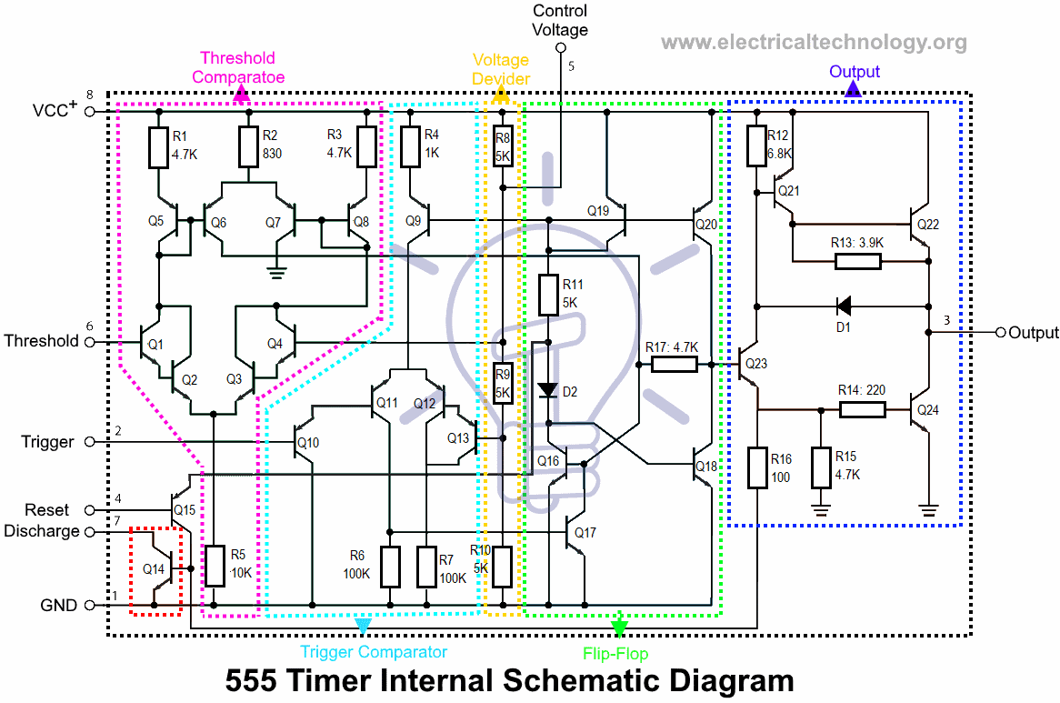
555 Timer IC - Types, Construction, Working & Application ... from www.electricaltechnology.org The 555 timer ic is an integrated circuit (chip) used in a variety of timer, delay, pulse generation, and oscillator applications. The ic can operate in three different modes such as astable, monotstable and bistable, because of which it can be adapted into many types of circuit designs like time delay circuits, pulse generation circuit, oscillator circuit and much more. The output voltage from the chip is around 1.5 v lower than vcc when high and around 0 v when low. Adjustable on off timer(using 555 astable mode) in this circuit a timer with cyclic on off operations is designed. Using the 555 timer ic in special or unusual circuits. This led will be switched on when button s1 is pressed and switched off when button s2 is pressed. Here, with the help of the 555 timer ic, we are eliminating the need of manually switching on or off the device. Ic 555 timer is a one of.
The working modes of a 555 timer are astable, bistable, and monostable.
500ms is the same as saying 0.5s so by rearranging the formula above, we get the calculated value for the resistor, r as: An arduino microcontroller is used to demonstrate usage. On pressing the switch s1, the ic will get the voltage and start its operation. This tutorial provides sample circuits to set up a 555 timer in monostable, astable, and bistable modes as well as an in depth discussion of how the 555 timer works and how to choose components to use with it. This low pulse lasts for 71.66 ms, giving a duty cycle of 99.53%. There are simple circuits for beginners and advanced engineers. Referring to the timing diagram in figure 3, a low voltage pulse applied to the trigger input (pin 2) causes the output voltage at pin 3 to go from low to high. The standard 555 timer ic is made of 2 diodes. Derivatives provide two or four timing circuits in one package.it was commercialized in 1972 by signetics. The output voltage from the chip is around 1.5 v lower than vcc when high and around 0 v when low. Ic 555 timer is a one of. The 555 timer is a simple integrated circuit that can be used to make many different electronic circuits. The operating voltage of this circuit is 9v.